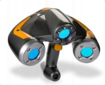
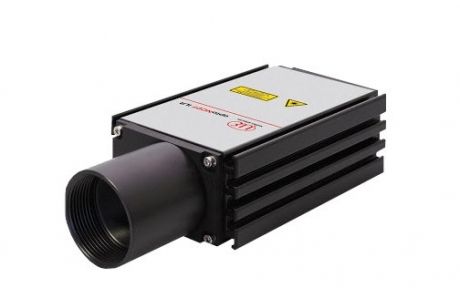
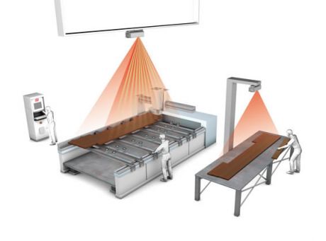
The 3D scanner allows you to manually import - capture a real model into a digital three-dimensional (3D) model in minutes. How to effectively use these devices and what are the possibilities of 3D scanning for a CNC milling machine?
How does the 3D scanner work? 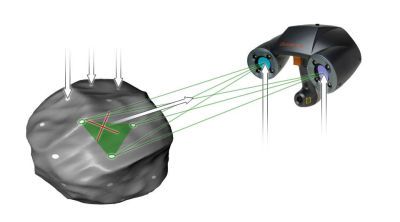
- Markers adjacent to the surface are applied randomly.
- CCD cameras track reference points and use triangulation to orient the points in space in real time
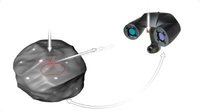 - Automatic generation of surfaces at the intersection of laser rays on the scanned surface
- A high-quality crossed laser beam scans the surface of the model
- Real-time loop between the scanner and the scanned object
Advantages of scanning models with a 3D scanner
1. Measurement speed
- Quick equipment preparation (connection, calibration)
- Collect large amounts of data in one minute
2. Ease of use
- No experience in 3D scanning is required
- The ability to easily share the device, e.g. for students
- Easy-to-use ZScan software
3. Versatility
- The size of the scanned elements does not matter
- Many uses in various fields
4. Ease of transport
- Scanning in various places and conditions
Reverse engineering - Making CAD models based on 3D scanning measurement
By making a 3D scan, we are able to obtain a digital image of any object, which can be further analyzed before CNC machining. The CAD model is the primary source of information for the engineer. The 3D scanner allows you to create a precise 3D solid that describes the entire geometry of the scanned detail. On its basis, an appropriate parametric model can be created.
- 3D modeling
- Tool development
- Assessment of compliance of the 3D model with the original
- Development of cooperating parts without 3D documentation from the manufacturer
Using 3D scanner in foundry
3D scanning is widely used in foundry. Precise 3D data of the entire geometry can be used in a variety of ways. How can you improve your casting processes and CNC machining of castings using a 3D scanner?
- Design and optimization of casting molds based on model elements
- Creation of CAD models of worn or undocumented parts
- Reconstruction of damaged cores
- Compare with CAD model or other part
- First piece inspection
- Non-contact verification of sand and wax cores
- Material thickness verification
- Mold wear verification
- Control of shrinkages, slopes and allowances
- Mold pouring simulations
- Analysis of assemblies of mating parts
- Inspection of gaps and angles
- Ensuring even heat dissipation
- Part clamping inspection
- Inspection of the machined casting
3D quality control of the finished part and mold
Accurate 3D data obtained by scanning allows you to easily and quickly verify the quality of the entire geometry of the core, casting or mold, thanks to the comparison with the nominal CAD model and presentation of the result in the form of a color deviation map. In addition, each element can be subjected to dimensional control, checking the compliance of individual features with the assumptions of 2D documentation.
3D scanners allow you to simulate the alignment of real mold halves and cores before starting the casting process. Such a virtual assembly of cooperating parts allows for the verification of gaps, angles, thickness of molding coatings and for simulating the casting process. Fast 3D scanning saves a lot of time and also improves the foundry process and thus increases the quality of the final product.
CNC machining is the last step in the production of the finished casting. The fixed element is milled - mechanical removal of excess material. Repetitive clamping of parts and verification of the milling process is essential.


